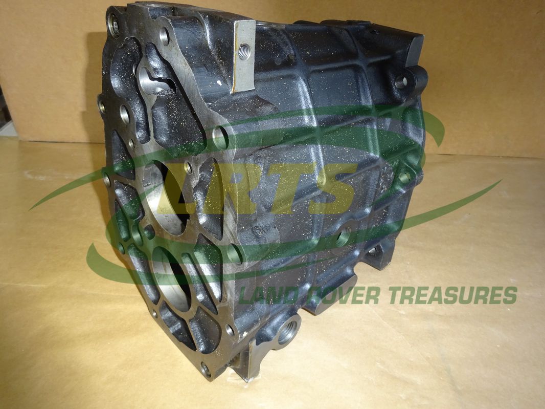
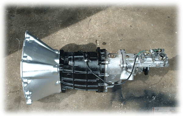
The LT77 gearbox can be identified as “Long Stick” as fitted to the Defender and “Short Stick” as fitted to the Disco. If your serial number starts with any of the following then you have a longstick: 50A, 51A, 52A, 56A, 60A, 61A. The 77 in LT77 represents the distances between the shaft centres. The 380 in R380 is the torque the gearbox was originally designed for, in Nm, it has been strengthened subsequently Pt1 LT77 and R380 Land Rover gearbox - Inner workings of the.
Some history of Land Rover gearboxes
A gearbox needs regular maintenance too. With the LT77 you should be looking to change the oil yearly at the very least, maybe more if you are clocking up high miles. The LT77 takes around 2.6 litres of oil, if you neglect to change or maintain your oil level in an old gearbox then you are just asking for something to go wrong. Tremec Gearbox Feature, LT77, R380 or the T5 Feature. Complete with our own in-house designed light weight Bell Housing, Internal concentric clutch slave cylinder with braided steel pipes, gearbox remote and clutch plate. The best gearbox money can buy! Related: lt77 gearbox sd1 lt77 gearbox defender r380 gearbox rover v8 engine classic cars lt77 gearbox 2wd rover v8 gearbox defender gearbox sd1 gearbox rover v8 manifold lt77 gearbox remote land rover lt77 gearbox.
Manual gearboxes from inception through 2007
The gearbox used in series Land Rovers was first used by Rover in 1932. This gearbox has undergone several modifications since then but is still basically the original design. This gearbox was considered advanced and strong when it was introduced and was finally discontinued because it could no longer be modified to hold up to the power and weight of newer Land Rovers.
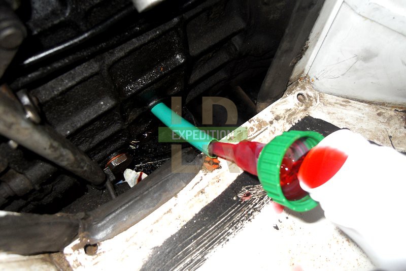
Lt77 Gearbox Oil

From 1948 (first LR production) to 1950 the gearbox had permanent 4WD with a freewheel device in the front prop shaft. From 1951 Rover fitted a transfer case with the now well known 'yellow and red knobs' right up through series III.
The dipstick and top oil fill disappeared with the introduction of the 'B' suffix gearbox. At that time the transfer case intermediate gear shaft diameter was increased for additional strength. In the autumn of 1963 the gearbox ratios and transfer case low gear ratio was changed with the introduction of the 'C' suffix (See my gear ratio web page for actual ratio numbers of the different series and Coiler gearbox & transfer cases).
In the Autumn of 1966 Rover introduced the '1 ton' 109' with the 6 cylinder petrol engine (A small number of 4 cyl models were made in 1970/71) . The 1 ton version had a lower ratio gearbox and transfer case to accommodate carrying a heavier load, and to compensate for the 9.00x16 tyres that came stock under the 1 ton model. One ton models also had ENV axles instead of the standard rover type. The 109 forward control Land Rovers used the same gearbox and transfer case.
The factory built a small number of all syncro series IIA gearboxes just prior to converting the box into the series III gearbox. The all syncro series IIA gearboxes can be identified by a 'S' prefix on the stamped number located on the transmission top cover. Since top covers can move about when multiple gearboxes are rebuilt, and a IIA gearbox is most likely to be rebuilt in the earlier documented style, the 'S' stamp on the top cover does not guarantee the gear box under the top cover is still all syncro.
The Series III gearbox has syncro in all gears as well as lower first and reverse gear ratios. The transfer case remained the same as was used on the late IIA. Series IIA gearboxes (D suffix & later) are generally considered to be stronger and longer lasting than early series III gearboxes (The ones imported into North America). Though a lot of this conception may have to do with people's shifting habits. Series III boxes prefer that you hesitate briefly in the neutral position while you shift gears. This puts less stress on the syncros and enhances their service life. Suffix letters on the Series III gearboxes restarted with suffix A.
There were changes made to the SIII gearbox during its 14 years of manufacture, mostly to make them less prone to wear and to keep them from jumping out of gear. The suffix D and later Series III gearboxes (manufactured after Land Rover left the US) have a one piece layshaft and are considered to be the most robust of all the Series Land Rover gearboxes. Other principal changes were to the reverse idler gear, bearing and shaft and the syncro units.
In general the Series gearbox is considered to be strong enough for about 120 HP, 160lbft is about the limit on torque. Early gearboxes are considered to be weaker than later IIA gearboxes. Early gearboxes tend to beak lay shafts and main shafts at the circlip groove positions. Late 2A lay shafts without the circlip groove are stronger than the early ones. According to Bob Shannon 'Here is the fix for the earlier gearboxes. The lay shaft from suffix D onwards gearboxes (part # 556040) has a stepped shoulder that fits into the rear of the D-onwards series lay shaft 2nd gear. So you don't have to buy a matching set of gears (D-onwards is part # 600916) you can take an earlier lay shaft gear from the pair (Suffix A-C is part # 245766) and machine out the relieved section to replicate the later gear's greater clearance. Also a suffix D lay shaft is probably cheaper than the suffixes A (part # 09917) and B-C (part #528703). Make sure the main shaft is set up correctly!!! ' And of course the SIII D suffix and newer gearboxes are considered to be the strongest of the lot.
The all syncro transmission has a reputation of being less robust than the earlier versions mostly because they do not hold up to quick shifting. The syncros must come to a stop when the shifter goes through the neutral position if the syncros are to last. When shifting an all syncro gearbox it is advised to hesitate just slightly in the centre of the 'H' pattern.
Now for the newer gearboxes:
This section is largely a rewording of an e-mail Mike Nieuwoudt published on the za-lro (Southern Africa) e-mail list. It is used with permission.

The 'recent' history of LR main gearboxes goes roughly as follows:
In the beginning when Rover needed a stronger gearbox for the new Range Rover and the 101 V8s they developed the LT95. During this time Rover was part of British Leyland so the LT stands for Leyland Transmission. '95' stands for the distance between the main and lay shafts in mm.
The LT 95 was a robust four speed gearbox with the transfer case built into the same enclosure (but they have different fluid reservoirs). One of the nice things about the LT95 was that there were a number of transfer case ratios available and you did not need to pull the box to change them. The gearbox was used on Range Rover through 1983, all 109 Stage 1 V8, all 101 and on 1983 and 1984 V8 Nineties and One Tens. The 101 LT95 is different from the unit used in the early RR or 110 V8s. The biggest difference is the bell housing and input shaft are shorter and the high ratio gear is pretty tall so, unless you're running big rubber you will run out of RPMs pretty quickly. The gear on the top of the box is very short as the 101 has a remote gear linkage. If you're putting it into a different Land Rover you will need to either modify the gear shift lever or source one from an early RR or 110 V8. The LT95 has a central diff so it powers both axles all the time. You'll need CV half shafts in the front axle. The center diff is lockable using a vacuum actuator. This requires a vacuum line to be run from the engine.
This gearbox uses 20/50 engine oil for both the gearbox and transfer case. This is apparently because it has it's own oil pump lubing the gearbox. A common mistake leading to early demise is running 90wt.
Starting with 1984 models Rover abandoned the LT95 four speed gearbox and went to five speed gearboxes, the LT77 and the LT85. The LT77 is the lighter duty of the pair. The LT85 was used on the V8 versions of the Ninety and One Ten. Since the LT77 is a 2WD passenger car gearbox, Rover added the LT230 transfer case for full time 4WD. (LT230? Yes, 230 mm parallel spacing between input and output shafts!)
1984 through 1990 When Rover (still part of British Leyland) decided to go to a five speed gearbox they picked the existing LT77 for use in certain vehicles. The LT77 is an updated version of an old Jaguar gearbox that found its way into current model British cars manufactured by British Leyland. Yes the distance between the main and lay shafts is 77 mm. There were two version of this gearbox. The earlier version is known as the short stick version. The later version, introduced around 1988 is known as the long stick version.
The Range Rover received the LT77 in 1984 because it was less expensive than the new LT85 and considered strong enough for the 3.5L V8 to use as a street cruising gearbox. The four cylinder Ninety and One Ten also received the LT77. When the Discovery was introduced it got the LT77 as well.
1984 through 1991: The LT85 (85 mm shaft spacing) was used in all V8 110 and 90 Land Rovers. The LT85 was originally designed under contract by Land Rover for Santana in Spain and was considered to be a strong working gearbox. Rover purchased LT85 gearboxes directly from Santana. It is also known as the Spanish Box. This gearbox was used as originally designed until 1988. A cost reduced, lighter weight, divided case version of the LT85 was introduced in 1988 and used through 1991. The main short coming of the divided case version was its main and lay shaft bearings. The loading on the bearings in 5th gear caused frequent gearbox failure when cruising for long periods of time under high throttle. There was also a bearing quality problem at one stage of manufacture and the gearbox was sensitive to the type of oil used.
In 1991 the relationship between Rover and Santana ended and the LT85 was no longer available to Rover. They needed to find a quick short term solution while they developed a new stronger gearbox.
1991 through 1993 The LT77S was introduced to the Defender V8 line and all models using the Tdi engine as an interim replacement for the no longer available LT85. The LT77S was a strengthened version of the LT77. The 'S' on the LT77S stands for 'Synchromesh'...it was modified for a 'smoother gear change'. The bell housings and input shafts of the LT77S differ between the V8 and Tdi due to Tdi's more aft location.
1994 to 2006: The R380 box was introduced as brand new LR gearbox across the entire Land Rover and Range Rover product lines. The R380 is a radically reworked LT77 (The 1940's Jag gearbox remember) with improved main shaft bearing arrangements that provided an overall strengthening of the box. The R380 name stands for 'Rated to 380 Nm input'. But the R380 still has the LT77's 77 mm shaft spacing. Since Rover was no longer part of British Leyland the LT prefix was abandoned.
The V8 and Tdi R380 gearboxes have different bell housings and primary input shafts. They will interchange by swapping these parts.
The R380 quickly got a bad name from gear problems and accelerated main shaft spline wear where it mates with the LT230 transfer case.

The LT230 accelerated main shaft spline wear problem had been present on all previous LT230 equipped Land-Rovers, irrespective of the gearbox it was mated to. This design problem was kept low key until a lot of customers complained about R380 problems.
A number of different fixes, such as slingers and special transfer case input shafts have been added to try solve the LT230 problem.
2007: Land Rover introduced the GFT MT 82 six-speed gearbox which provides a much wider ratio spread than previous 5 speed gearboxes. The GFT MT 82 has a lower first gear and the new sixth gear is 20 per cent higher than the outgoing model’s fifth gear.
A little Automatic history
1982: the Chrysler 3 speed automatic transmission was introduced into the Range Rover product line.
Lt77 Gearbox Rebuild
1988: The Range Rover is offered with EFI and the ZF H4 four speed automatic transmission.
2007: Land Rover introduced the ZF HP26 six speed automatic transmission with a wider ratio range than previous Land Rover options.

Lt77 Gearbox Oil
This part of site is an attempt to organize and add to the web resources for the Rover SD1 to form a cohesive and easily usable guide for those of us without easy access to expert repair and/or advice. It is not offered in any way as a definitive source and we take no responsibility for any errors that may exist. |

Introduction The need for an overdrive gear ratio is catered for in our 77 mill. gearbox which features a .833:1 5th gear. Incidentally, the name 77 mill. is derived from the distance between the mainshaft and the layshaft. |
We start with the box drained of oil and removed from the car, in this case a Rover. First unscrew the clutch release pivot bolt, using ST1 136, and withdraw the release lever and slipper pads and the release bearing and support sleeve then remove the bell housing. |
To remove the rear cover, first remove the drive flange and the speedometer driven gear and housing the locating boss for the rear selector spool and the ten retaining bolts and spring washers. |
Remove the mainshaft circlip then the support plate and the synchro-hub and sleeve. If the hub is tight, it can be levered off using two small tyre levers. |
Then the two dummy bolts from the centre plate. |
Slide the reverse gear and distance piece from the reverse shaft. The shaft need only be removed if either it or the centre plate are being replaced. In the case of centre plate replacement, the locating dowels and the reverse pivot shaft must also be removed. |
